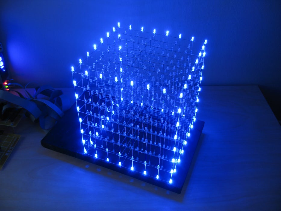
We believe this Instructable is the most comprehensive step-by-step guide to build an 8x8x8 LED Cube ever published on the intertubes. It will teach you everything from theory of operation, how to build the cube, to the inner workings of the software. We will take you through the software step by step, both the low level drivers/routines and how to create awesome animations. The software aspect of LED cubes is often overlooked, but a LED cube is only as awesome as the software it runs.
About halfway through the Instructable, you will actually have a fully functional LED cube. The remaining steps will show you how to create the software.
Step 1: Skills Required
I've been doing electronics for a long time, and for years i struggled with analog circuits. The analog circuits failed over half the time even if i followed instructions. One resistor or capacitor with a slightly wrong value, and the circuit doesn't work.
About 4 years ago, I decided to give microcontrollers a try. This completely changed my relationship with electronics. I went from only being able to build simple analog circuits, to being able to build almost anything!
A digital circuit doesn't care if a resistor is 1k ohm or 2k ohm, as long as it can distinguish high from low. And believe me, this makes it A LOT easier to do electronics!
With that said, there are still some things you should know before venturing out and building this rather large project.
You should have an understanding of:
- Basic electronics. (We would recommend against building this as your very first electronics project. But please read the Instructable. You'll still learn a lot!)
- How to solder.
- How to use a multimeter etc.
- Writing code in C (optional. We provide a fully functional program, ready to go)
Step 2: Component List
- 512x LEDs (plus some extra for making mistakes!)
- 64x resistors. (see separate step for ohm value)
- 1x or 2x large prototype PCBs. The type with copper "eyes", see image.
- 1x ATmega32 microcontroller (you can also use the pin-compatible ATmega16)
- 3x status LEDs. You choose color and size.
- 3x resistors for the status LEDs.
- 8x 74HC574 ICs
- 16x PN2222 transistors
- 16x 1k resistors
- 1x 74HC138 IC
- 1x Maxim MAX232 IC
- 1x 14.7456 MHz crustal
- 2x 22pF ceramic capacitors
- 16x 0.1uF ceramic capacitors
- 3x 1000uF electrolytic capacitor
- 3x 10uF electrolytic capacitor
- 1x 100uF electrolytic capacitors
- 8x 20 pin IC sockets
- 1x 40 pin IC socket
- 2x 16 pin IC socket
- 1x 2-pin screw terminal
- 1x 2wire cable with plugs
- 9x 8-pin terminal pins
- 1x 4-pin terminal pins, right angle
- 2x 16-pin ribbon cable connector
- 1x 10-pin ribbon cable connector
- Ribbon cable
- 2x pushbuttons
- 2x ribbon cable plugs
- 9x 8-pin female header plugs
- Serial cable and 4pin female pin header
- Piece of wood for template and base
- 8x optional pull-up resistors for layers
- 5v power supply (see separate step for power supply)
Step 4: What Is a LED Cube
A LED cube is like a LED screen, but it is special in that it has a third dimension, making it 3D. Think of it as many transparent low resolution displays. In normal displays it is normal to try to stack the pixels as close as possible in order to make it look better, but in a cube one must be able to see trough it, and more spacing between the pixels (actually it's voxels since it is in 3d) is needed. The spacing is a trade-off between how easy the layers behind it is seen, and voxel fidelity.
Since it is a lot more work making a LED cube than a LED display, they are usually low resolution. A LED display of 8x8 pixels is only 64 LEDs, but a LED cube in 8x8x8 is 512 LEDs, an order of magnitude harder to make! This is the reason LED cubes are only made in low resolution.
A LED cube does not have to be symetrical, it is possible to make a 7x8x9, or even oddly shaped ones.
Step 5: How Does a LED Cube Work
Instead, LED cubes rely on an optical phenomenon called persistence of vision (POV).
If you flash a led really fast, the image will stay on your retina for a little while after the led turns off.
By flashing each layer of the cube one after another really really fast, it gives the illusion of a 3d image, when int fact you are looking at a series of 2d images stacked ontop oneanother. This is also called multiplexing.
With this setup, we only need 64 (for the anodes) + 8 (for each layer) IO ports to control the LED cube.
In the video, the process is slowed down enough for you to see it, then it runs faster and faster until the refresh rate is fast enough for the camera to catch the POV effect.
Step 6: The Anatomy of a LED Cube
We are going to be talking about anodes, cathodes, columns and layers, so lets take a moment to get familiar with the anatomy of a LED cube.
An LED has two legs. One positive (the anode) and one negative (cathode). In order to light up an LED, you have to run current from the positive to the negative leg. (If i remember correctly the actual flow of electrons is the other way around. But let's stick to the flow of current which is from positive to negative for now).
The LED cube is made up of columns and layers. The cathode legs of every LED in a layer are soldered together. All the anode legs in one column are soldered together.
Each of the 64 columns are connected to the controller board with a separate wire. Each column can be controlled individually. Each of the 8 layers also have a separate wire going to the controller board.
Each of the layers are connected to a transistor that enables the cube to turn on and off the flow of current through each layer.
By only turning on the transistor for one layer, current from the anode columns can only flow through that layer. The transistors for the other layers are off, and the image outputted on the 64 anode wires are only shown on the selected layer.
To display the next layer, simply turn off the transistor for the current layer, change the image on the 64 anode wires to the image for the next layer. Then turn on the transistor for the next layer. Rinse and repeat very very fast.
The layers will be referred to as layers, cathode layers or ground layers.
The columns will be referred to as columns, anode columns or anodes.
Step 7: Cube Size and IO Port Requirements
To drive a LED cube, you need two sets of IO ports. One to source all the LED anode columns, and one to sink all the cathode layers.
For the anode side of the cube, you'll need x^2 IO ports, where x^3 is the size of your LED cube. For an 8x8x8 (x=8), you need 64 IO ports to drive the LED anodes. (8x8). You also need 8 IO ports to drive the cathodes.
Keep in mind that the number of IO ports will increase exponentially. So will the number of LEDs. You can see a list of IO pin requirement for different cube sizes in table 1.
For a small LED cube, 3x3x3 or 4x4x4, you might get away with connecting the cathode layers directly to a micro controller IO pin. For a larger cube however, the current going through this pin will be too high. For an 8x8x8 LED cube with only 10mA per LED, you need to switch 0.64 Ampere. See table 2 for an overview of power requirements for a LED layer of different sizes. This table shows the current draw with all LEDs on.
If you are planning to build a larger cube than 8x8x8 or running each LED at more than 10-ish mA, remember to take into consideration that your layer transistors must be able to handle that load.
Step 8: IO Port Expansion, More Multiplexing
We gathered from the last step that an 8x8x8 LED cube requires 64+8 IO lines to operate. No AVR micro controller with a DIP package (the kind of through hole chip you can easily solder or use in a breadboard, Dual Inline Package) have that many IO lines available.
To get get the required 64 output lines needed for the LED anodes, we will create a simple multiplexer circuit. This circuit will multiplex 11 IO lines into 64 output lines.
The multiplexer is built by using a component called a latch or a flip-flop. We will call them latches from here on.
This multiplexer uses an 8 bit latch IC called 74HC574. This chip has the following pins:
- 8 inputs (D0-7)
- 8 outputs (Q0-7)
- 1 "latch" pin (CP)
- 1 output enable pin (OE)
The job of the latch is to serve as a kind of simple memory. The latch can hold 8 bits of information, and these 8 bits are represented on the output pins. Consider a latch with an LED connected to output Q0. To turn this LED on, apply V+ (1) to input D0, then pull the CP pin low (GND), then high (V+).
When the CP pin changes from low to high, the state of the input D0 is "latched" onto the output Q0, and this output stays in that state regardless of future changes in the status of input D0, until new data is loaded by pulling the CP pin low and high again.
To make a latch array that can remember the on/off state of 64 LEDs we need 8 of these latches. The inputs D0-7 of all the latches are connected together in an 8 bit bus.
To load the on/off states of all the 64 LEDs we simply do this: Load the data of the first latch onto the bus. pull the CP pin of the first latch low then high. Load the data of the second latch onto the bus. pull the CP pin of the second latch low then high. Load the data of the third latch onto the bus. pull the CP pin of the third latch low then high. Rinse and repeat.
The only problem with this setup is that we need 8 IO lines to control the CP line for each latch. The solution is to use a 74HC138. This IC has 3 input lines and 8 outputs. The input lines are used to control which of the 8 output lines that will be pulled low at any time. The rest will be high. Each out the outputs on the 74HC138 is connected to the CP pin on one of the latches.
The following pseudo-code will load the contents of a buffer array onto the latch array:
// PORT A = data bus
// PORT B = address bus (74HC138)
// char buffer[8] holds 64 bits of data for the latch array
PORTB = 0x00; // This pulls CP on latch 1 low.
for (i=0; i < 8; i++)
{
PORTA = buffer[i];
PORTB = i+1;
}
The outputs of the 74HC138 are active LOW. That means that the output that is active is pulled LOW. The latch pin (CP) on the latch is a rising edge trigger, meaning that the data is latched when it changes from LOW to HIGH. To trigger the right latch, the 74HC138 needs to stay one step ahead of the counter i. If it had been an active HIGH chip, we could write PORTB = i; You are probably thinking, what happens when the counter reaches 7, that would mean that the output on PORTB is 8 (1000 binary)on the last iteration of the for() loop. Only the first 8 bits of PORT B are connected to the 74HC138. So when port B outputs 8 or 1000 in binary, the 74HC138 reads 000 in binary, thus completing its cycle. (it started at 0). The 74HC138 now outputs the following sequence: 1 2 3 4 5 6 7 0, thus giving a change from LOW to HIGH for the current latch according to counter i.
Step 9: IO Port Expansion, Alternative Solution
You can also use a serial-in-parallel out shift register to get 64 output lines. 74HC164 is an 8 bit shift register. This chip has two inputs (may also have an output enable pin, but we will ignore this in this example).
- data
- clock
The way you would normally load data into a chip like this, is to take a byte and bit-shift it into the chip one bit at a time. This uses a lot of CPU cycles. However, we have to use 8 of these chips to get our desired 64 output lines. We simply connect the data input of each shift register to each of the 8 bits on a port on the micro controller. All the clock inputs are connected together and connected to a pin on another IO port.
This setup will use 9 IO lines on the micro controller.
In the previous solution, each byte in our buffer array was placed in it's own latch IC. In this setup each byte will be distributed over all 8 shift registers, with one bit in each.
The following pseudo-code will transfer the contents of a 64 bit buffer array to the shift registers.
// PORT A: bit 0 connected to shift register 0's data input, bit 1 to shift register 1 and so on.
// PORT B: bit 0 connected to all the clock inputs
// char buffer[8] holds 64 bits of data
for (i=0; i < 8; i++)
{
PORTB = 0x00; // Pull the clock line low, so we can pull it high later to trigger the shift register
PORTA = buffer[i]; // Load a byte of data onto port A
PORTB = 0x01; // Pull the clock line high to shift data into the shift registers.
This is perhaps a better solution, but we had to use what we had available when building the cube. For the purposes of this instructable, we will be using a latch based multiplexer for IO port expansion. Feel free to use this solution instead if you understand how they both work.
With this setup, the contents of the buffer will be "rotated" 90 degrees compared to the latch based multiplexer. Wire up your cube accordingly, or simply just turn it 90 degrees to compensate ;)
Step 10: Power Supply Considerations
This step is easy to overlook, as LEDs themselves don't draw that much current. But remember that this circuit will draw 64 times the mA of your LEDs if they are all on. In addition to that, the AVR and the latch ICs also draws current.
To calculate the current draw of your LEDs, connect a led to a 5V power supply with the resistor you intend to use, and measure the current in mA. Multiply this number by 64, and you have the power requirements for the cube itself. Add to that 15-20 mA for the AVR and a couple of mA for each latch IC.
Our first attempt at a power supply was to use a step-down voltage regulator, LM7805, with a 12V wall wart. At over 500mA and 12V input, this chip became extremely hot, and wasn't able to supply the desired current.
We later removed this chip, and soldered a wire from the input to the output pin where the chip used to be.
We now use a regulated computer power supply to get a stable high current 5V supply.
Step 11: Buy a Power Supply
eBay is a great place to buy these things.
Search for "5v power supply" and limit the search to "Business & Industrial", and you'll get a lot of suitable power supplies. About 15 bucks will get you a nice PSU.
Step 12: Build a Power Supply
A couple of years before we built the LED cube, we made our self a nice little lab power supply from an old external SCSI drive. This is what we have been using to power the LED cube.
PC power supplies are nice, because they have regulated 12V and 5V rails with high Ampere ratings.
You can use either a regular AT or ATX power supply or and old external hard drive enclosure.
If you want to use an ATX power supply, you have to connect the green wire on the motherboard connector to ground (black). This will power it up.
External hard drive enclosures are especially nice to use as power supplies. They already have a convenient enclosure. The only thing you have to do is to add external power terminals.
Power supplies have a lot of wires, but the easiest place to get the power you need is through a molex connector. That is the kind of plug you find on hard drives (before the age of S-ATA).
Black is GND Yellow is +12V Red is +5V
Here is an image of our lab PSU. We have 12V output, 5V output with an ampere meter and 5V output without an ampere meter. We use the second 5V output to power an 80mm PC fan to suck or blow fumes away when we solder.
We won't get into any more details of how to make a power supply here. I'm sure you can find another instructable on how to do that.
Step 13: Choose Your LEDs
There are many things to consider when choosing LEDs.
1)
You want the LED cube to be equally visible from all sides. Therefore we strongly recommend using diffused LEDs. A clear LED will shoot the majority of it's light out the top of the LED. A diffused LED will be more or less equally bright from all sides. Clear LEDs also create another problem. If your cube is made up of clear LEDs. The LEDs will also partially illuminate the LEDs above them, since most of the light is directed upwards. This creates some unwanted ghosting effects.
We actually ordered diffused LEDs from eBay, but got 1000 clear LEDs instead. Shipping them back to China to receive a replacement would have taken too much time, so we decided to used the clear LEDs instead. It works fine, but the cube is a lot brighter when viewed from the top as opposed to the sides.
The LEDs we ordered from eBay were actually described as "Defused LEDs". Maybe we should have taken the hint ;) Defusing is something you do to a bomb when you want to prevent it from blowing up, hehe.
2)
Larger LEDs gives you a bigger and brighter pixel, but since since the cube is 8 layers deep, you want enough room to see all the way through to the furthest level. We went with 3mm LEDs because we wanted the cube to be as "transparent" as possible. Our recommendation is to use 3mm diffused LEDs.
3)
You can buy very cheap lots of 1000 LEDs on eBay. But keep in mind that the quality of the product may be reflected in it's price. We think that there is less chance of LED malfunction if you buy better quality/more expensive LEDs.
4)
Square LEDs would probably look cool to, but then you need to make a soldering template that can accommodate square LEDs. With 3mm round LEDs, all you need is a 3mm drill bit.
5)
Since the cube relies on multiplexing and persistence of vision to create images, each layer is only turned on for 1/8 of the time. This is called a 1/8 duty cycle. To compensate for this, the LEDs have to be bright enough to produce the wanted brightness level at 1/8 duty cycle.
6)
Leg length. The cube design in this instructable uses the legs of the LEDs themselves as the skeleton for the cube. The leg length of the LEDs must be equal to or greater than the distance you want between each LED.
Step 14: Choose Your Resistors
There are three things to consider when choosing the value of your resistors, the LEDs, the 74HC574 that drive the LEDs, and the transistors used to switch the layers on and off.
1)
If your LEDs came with a data sheet, there should be some ampere ratings in there. Usually, there are two ratings, one mA for continuous load, and mA for burst loads. The LEDs will be running at 1/8 duty cycle, so you can refer to the burst rating.
2)
The 74HC574 also has some maximum ratings. If all the LEDs on one anode column are on, this chip will supply current 8/8 of the time. You have to keep within the specified maximum mA rating for the output pins. If you look in the data sheet, You will find this line: DC Output Source or Sink Current per Output Pin, IO: 25 mA. Also there is a VCC or GND current maximum rating of 50mA. In order not to exceed this, your LEDs can only run at 50/8 mA since the 74HC574 has 8 outputs. This gives you 6.25 mA to work with.
3)
The transistors have to switch on and off 64 x the mA of your LEDs. If your LEDs draw 20mA each, that would mean that you have to switch on and off 1.28 Ampere.
The only transistors we had available had a maximum rating of 400mA.
We ended up using resistors of 100 ohms.
Step 15: Choose the Size of Your Cube
We wanted to make the LED cube using as few components as possible. We had seen some people using metal rods for their designs, but we didn't have any metal rods. Many of the metal rod designs also looked a little crooked.
We figured that the easiest way to build a led cube would be to bend the legs of the LEDs so that the legs become the scaffolding that holds the LEDs in place.
We bent the cathode leg on one of the LEDs and measured it to be 26 mm from the center of the LED. By choosing a LED spacing of 25mm, there would be a 1mm overlap for soldering. (1 inch = 25.4mm)
With a small 3mm LED 25mm between each led gave us plenty of open space inside the cube. Seeing all the way through to the furthest layer wouldn't be a problem. We could have made the cube smaller, but then we would have to cut every single leg, and visibility into the cube would be compromised.
Our recommendation is to use the maximum spacing that your LED can allow. Add 1mm margin for soldering.
Step 16: How to Make Straight Wire
Our first attempt at this failed horribly. We tried to bend it into a straight wire, but no matter how much we bent, it just wasn't straight enough.
Then we remembered an episode of "How it's made" from the Discovery Channel. The episode was about how they make steel wire. They start out with a spool of really thick wire, then they pull it through smaller and smaller holes. We remembered that the wire was totally straight and symmetrical after being pulled like that.
So we figured we should give pulling a try, and it worked! 100% straight metal wire from a spool!
Here is how you do it.
- cut of the length of wire you need from the spool, plus an inch or two.
- Remove the insulation, if any.
- Get a firm grip of each end of the wire with two pairs of pliers
- Pull hard!
- You will feel the wire stretch a little bit.
Step 17: Practice in Small Scale
Whenever Myth Busters are testing a complex myth, they start by some small scale experiments.
We recommend that you do the same thing.
Before we built the 8x8x8 LED cube, we started by making a smaller version of it, 4x4x4. By making the 4x4x4 version first, you can perfect your cube soldering technique before starting on the big one.
Check out our 4x4x4 LED cube instructable for instructions on building a smaller "prototype".
Step 18: Build the Cube: Create a Jig
In order to make a nice looking LED cube, it is important that it is completely symmetrical, that the space between each LED is identical, and that each LED points the same way. The easiest way to accomplish this is to create a temporary soldering jig/template.
1)
Find a piece of wood or plastic that is larger than the size of your cube.
2)
Find a drill bit that makes a hole that fits a LED snugly in place. You don't want it to be to tight, as that would make it difficult to remove the soldered layer from the jig without bending it. If the holes are too big, some of the LEDs might come out crooked.
3)
Use a ruler and an angle iron to draw up a grid of 8 by 8 lines intersecting at 64 points, using the LED spacing determined in a previous step.
4)
Use a sharp pointy object to make indentions at each intersection. These indentions will prevent the drill from sliding sideways when you start drilling.
5)
Drill out all the holes.
6)
Take an LED and try every hole for size. If the hole is too snug, carefully drill it again until the LED fits snugly and can be pulled out without much resistance.
7)
Somewhere near the middle of one of the sides, draw a small mark or arrow. A steel wire will be soldered in here in every layer to give the cube some extra stiffening.
Step 19: Build the Cube: Soldering Advice
You are going to be soldering VERY close to the LED body, and you are probably going to be using really cheap LEDs from eBay. LEDs don't like heat, cheap LEDs probably more so than others. This means that you have to take some precautions in order to avoid broken LEDs.
Soldering iron hygiene
First of all, you need to keep your soldering iron nice and clean. That means wiping it on the sponge every time you use it. The tip of your soldering iron should be clean and shiny. Whenever the you see the tip becoming dirty with flux or oxidizing, that means loosing it's shinyness, you should clean it. Even if you are in the middle of soldering. Having a clean soldering tip makes it A LOT easier to transfer heat to the soldering target.
Soldering speed
When soldering so close to the LED body, you need to get in and out quickly. Wipe your iron clean. Apply a tiny amount of solder to the tip. Touch the part you want to solder with the side of your iron where you just put a little solder. Let the target heat up for 0.5-1 seconds, then touch the other side of the target you are soldering with the solder. You only need to apply a little bit. Only the solder that is touching the metal of both wires will make a difference. A big blob of solder will not make the solder joint any stronger. Remove the soldering iron immediately after applying the solder.
Mistakes and cool down
If you make a mistake, for example if the wires move before the solder hardens or you don't apply enough solder. Do not try again right away. At this point the LED is already very hot, and applying more heat with the soldering iron will only make it hotter. Continue with the next LED and let it cool down for a minute, or blow on it to remove some heat.
Solder
We recommend using a thin solder for soldering the LEDs. This gives you a lot more control, and enable you to make nice looking solder joints without large blobs of solder. We used a 0.5 mm gauge solder. Don't use solder without flux. If your solder is very old and the flux isn't cleaning the target properly, get newer solder. We haven't experienced this, but we have heard that it can happen.
Are we paranoid?
When building the 8x8x8 LED Cube, we tested each and every LED before using it in the cube. We also tested every LED after we finished soldering a layer. Some of the LEDs didn't work after being soldered in place. We considered these things before making a single solder joint. Even with careful soldering, some LEDs were damaged.
The last thing you want is a broken LED near the center of the cube when it is finished. The first and second layer from the outside can be fixed afterwards, but any further in than that, and you'll need endoscopic surgical tools ;)
Step 20: Build the Cube: Test the LEDs
We got our LEDs from eBay, really cheap!
We tested some of the LED before we started soldering, and randomly stumbled on a LED that was a lot dimmer than the rest. So we decided to test every LED before using it. We found a couple of dead LEDs and some that were dimmer than the rest.
It would be very bad to have a dim LED inside your finished LED cube, so spend the time to test the LEDs before soldering! This might be less of a problem if you are using LEDs that are more expensive, but we found it worth while to test our LEDs.
Get out your breadboard, connect a power supply and a resistor, then pop the LEDs in one at a time. You might also want to have another LED with its own resistor permanently on the breadboard while testing. This makes it easier to spot differences in brightness.
Step 21: Build the Cube: Solder a Layer
Each layer is made up of 8 columns of LEDs held together by the legs of each LED. At the top of each layer each LED is rotated 90 degrees clockwise, so that the leg connects with the top LED of the next column. On the column to the right this leg will stick out of the side of the layer. We leave this in place and use it to connect ground when testing all the LEDs in a later step.
1) Prepare 64 LEDs
Bend the cathode leg of each LED 90 degrees. Make sure the legs are bent in the same direction on all the LEDs. Looking at the LED sitting in a hole in the template with the notch to the right, we bent the leg upwards.
2) Start with the row at the top
Start by placing the top right LED in the template. Then place the one to the left, positioning it so that it's cathode leg is touching the cathode leg of the previous LED. Rinse and repeat until you reach the left LED. Solder all the joints.
3) Solder all 8 columns
If you are right handed, we recommend you start with the column to the left. That way your hand can rest on the wooden template when you solder. You will need a steady hand when soldering freehand like this. Start by placing the LED second from the top, aligning it so it's leg touches the solder joint from the previous step. Then place the LED below that so that the cathode leg touches the LED above. Repeat until you reach the bottom. Solder all the joints.
4) Add braces
You now have a layer that looks like a comb. At this point the whole thing is very flimsy, and you will need to add some support. We used one bracing near the bottom and one near the middle. Take a straight peace of wire, roughly align it where you want it and solder one end to the layer. Fine tune the alignment and solder the other end in place. Now, make solder joints to the remaining 6 columns. Do this for both braces.
5) Test all the LEDs
This is covered in the next step. Just mentioning here so you don't remove the layer just yet.
6) Remove the layer
The first layer of your LED cube is all done, now all you have to do is remove it from the template. Depending on the size of your holes, some LEDs might have more resistance when you try to pull it out. Simply grabbing both ends of the layer and pulling would probably break the whole thing if a couple of the LEDs are stuck.
Start by lifting every single LED a couple of millimeters. Just enough to feel that there isn't any resistance. When all the LEDs are freed from their holes, try lifting it carefully. If it is still stuck, stop and pull the stuck LEDs out.
Repeat 8 times!
Note on images:
If you are having trouble seeing the detail in any of our pictures, you can views the full resolution by clicking on the little i icon in the top left corner of every image. All our close up pictures are taken with a mini tripod and should have excellent macro focus. On the image page, choose the original size from the "Available sizes" menu on the left hand side.
Step 22: Build the Cube: Test the Layer
Soldering that close to the body of the LED can damage the electronics inside. We strongly recommend that you test all LEDs before proceeding.
Connect ground to the tab you left sticking out at the upper right corner. Connect a wire to 5V through a resistor. Use any resistor that lights the LED up and doesn't exceed its max mA rating at 5V. 470 Ohm would probably work just fine.
Take the wire and tap it against all 64 anode legs that are sticking up from your template. If a LED doesn't flash when you tap it, that means that something is wrong.
1) Your soldering isn't conducting current.
2) The LED was overheated and is broken.
3) You didn't make a proper connection between the test wire and the led. (try again).
If everything checks out, pull the layer from the cube and start soldering the next one.
Step 23: Build the Cube: Straigthen the Pins
In our opinion, a LED cube is a piece of art and should be perfectly symmetrical and straight. If you look at the LEDs in your template from the side, they are probably bent in some direction.
You want all the legs to point straight up, at a 90 degree angle from the template.
While looking at the template from the side, straighten all the legs. Then rotate the template 90 degrees, to view it from the other side, then do the same process.
You now have a perfect layer that is ready to be removed from the template.
Step 24: Build the Cube: Bend the Pins
In the LED cube columns, we want each LED to sit centered precisely above the LEDs below. The legs on the LEDs come out from the LED body half a millimeter or so from the edge. To make a solder joint, we have to bend the anode leg so that it touches the anode leg on the LED below.
Make a bend in the anode leg towards the cathode leg approximately 3mm from the end of the leg. This is enough for the leg to bend around the LED below and make contact with it's anode leg.
Step 25: Build the Cube: Solder the Layers Together
Now comes the tricky part, soldering it all together!
The first two layers can be quite flimsy before they are soldered together. You may want to put the first layer back in the template to give it some stability.
In order to avoid total disaster, you will need something to hold the layer in place before it is soldered in place. Luckily, the width of a 9V battery is pretty close to 25 mm. Probably closer to 25.5-26mm, but that's OK.
Warning: The 9 volts from a 9V battery can easily overload the LEDs if the contacts on the battery comes in contact with the legs of the LEDs. We taped over the battery poles to avoid accidentally ruining the LEDs we were soldering.
We had plenty of 9V batteries lying around, so we used them as temporary supports.
Start by placing a 9V battery in each corner. Make sure everything is aligned perfectly, then solder the corner LEDs.
Now solder all the LEDs around the edge of the cube, moving the 9V batteries along as you go around. This will ensure that the layers are soldered perfectly parallel to each other.
Now move a 9V battery to the middle of the cube. Just slide it in from one of the sides. Solder a couple of the LEDs in the middle.
The whole thing should be pretty stable at this point, and you can continue soldering the rest of the LEDs without using the 9V batteries for support.
However, if it looks like some of the LEDs are sagging a little bit, slide in a 9V battery to lift them up!
When you have soldered all the columns, it is time to test the LEDs again. Remember that tab sticking out from the upper right corner of the layer, that we told you not to remove yet? Now it's time to use it. Take a piece of wire and solder the tab of the bottom layer to the tab of the layer you just soldered in place.
Connect ground to the the ground tab.
Test each led using the same setup as you used when testing the individual layers. Since the ground layers have been connected by the test tabs, and all the anodes in each columns are connected together, all LEDs in a column should light up when you apply voltage to the top one. If the LEDs below it does not light up, it probably means that you forgot a solder joint! It is A LOT better to figure this out at this point, rather than when all the layers are soldered together. The center of the cube is virtually impossible to get to with a soldering iron.
You now have 2/8 of your LED cube soldered together! Yay!
For the next 6 layers, use the exact same process, but spend even more time aligning the corner LEDs before soldering them. Look at the cube from above, and make sure that all the corner LEDs are on a straight line when looking at them from above.
Rinse and repeat!
Step 26: Build the Cube: Create the Base
We didn't have any fancy tools at our disposal to create a fancy stand or box for our LED cube. Instead, we modified the template to work as a base for the cube.
We encourage you to make something cooler than we did for your LED cube!
For the template, we only drilled a couple of mm into the wood. To transform the template into a base, we just drilled all the holes through the board. Then we drilled 8 smaller holes for the 8 cathode wires running up to the 8 cathode layers.
Of course, you don't want to have your LED cube on a wood colored base. We didn't have any black paint lying around, but we did find a giant black magic marker! Staining the wood black with a magic marker worked surprisingly well! I think the one we used had a 10mm point.
Step 27: Build the Cube: Mount the Cube
Mount the cube. That sounds very easy, but it's not. You have to align 64 LED legs to slide through 64 holes at the same time. It's like threading a needle, times 64.
We found it easiest to start with one end, then gradually popping the legs into place. Use a pen or something to poke at the LED legs that miss their holes.
Once all 64 LED legs are poking through the base, carefully turn it on it's side. Then bend all 64 legs 90 degrees. This is enough to hold the cube firmly mounted to the base. No need for glue or anything else.
Step 28: Build the Cube: Cathode Risers
You now have a LED cube with 64 anode connections on the underside of the base. But you need to connect the ground layers too.
Remember those 8 small holes you drilled in a previous step? We are going to use them now.
Make some straight wire using the method explained in a previous step.
We start with ground for layer 0. Take a short piece of straight wire, Make a bend approximately 10mm from the end. Poke it through the hole for ground layer 0. Leave 10mm poking through the underside of the base. Position it so that the bend you made rests on the back wire of ground layer 0. Now solder it in place.
Layer 1 through 7 are a little trickier. We used a helping hand to hold the wire in place while soldering.
Take a straight piece of wire and bend it 90 degrees 10mm from the end. Then cut it to length so that 10mm of wire will poke out through the underside of the base.
Poke the wire through the hole and let the wire rest on the back wire of the layer you are connecting. Clamp the helping hand onto the wire, then solder it in place.
Rinse and repeat 7 more times.
Carefully turn the cube on it's side and bend the 8 ground wires 90 degrees.
Step 29: Build the Cube: Attach Cables
64+8 wires have to go from the controller to the LED cube. We used ribbon cable to make things a little easier.
The ground layers use an 8-wire ribbon cable.
The cathodes are connected with 4 16-wire ribbon cables. Each of these ribbon cables are split in two at either end, to get two 8-wire cables.
At the controller side, we attached 0.1" female header connectors. These plug into standard 0.1" single row PCB header pins.
The header connector is a modular connector that comes in two parts, metal inserts and a plastic body.
The metal inserts are supposed to be crimped on with a tool. We didn't have the appropriate tool on hand, so we used pliers. We also added a little solder to make sure the wires didn't fall of with use.
1) Prepare one 8-wire ribbon cable and 4 16-wire ribbon cables of the desired length
2) Crimp or solder on the metal inserts.
3) Insert the metal insert into the plastic connector housing.
4) Solder the 8-wire ribbon cable to the cathode risers. Pre-tin the cables before soldering!
5) Solder in the rest of the cables. The red stripe on the first wire indicates that this is bit 0.
6) Tighten the screws on the strain relief to make sure everything stays in place.
7) Connect all the ribbon cables to the PCBs in the correct order. See pictures below. Our 8 wire ribbon cable didn't have a red wire. Just flip the connector 180 degrees if your cube is upside-down.
Step 30: Build the Controller: Layout
We took out the biggest type of PCB we had available (9x15cm) and started experimenting with different board layouts. It soon became clear that cramming all the components onto one board wasn't a good solution. Instead we decided to separate the latch array and power supply part of the circuit and place it on a separate board. A ribbon cable transfers data lines between the two boards.
Choosing two separate boards was a good decision. The latch array took up almost all the space of the circuit board. There wouldn't have been much space for the micro controller and other parts.
You may not have the exact same circuit boards as we do, or may want to arrange your components in a different way. Try to place all the components on your circuit board to see which layout best fits your circuit board.
Attachments
Step 31: Build the Controller: Clock Frequency
You may be thinking that this is an odd number to use, and why we didn't run the ATmega at the 16MHz it is rated for.
We want to be able to control the LED cube from a computer, using RS232. Serial communication requires precise timing. If the timing is off, only by a little bit, some bits are going to be missed or counted double from time to time. We won't be running any error correcting algorithms on the serial communications, so any error over the line would be represented in the LED cube as a voxel being on or off in the wrong place.
To get flawless serial communication, you have to use a clock frequency that can be divided by the serial frequency you want to use.
14.7456 MHz is dividable by all the popular RS232 baud rates.
- (14.7456MHz*1000*1000) / 9600 baud = 1536.0
- (14.7456MHz*1000*1000) / 19200 baud = 768.0
- (14.7456MHz*1000*1000) / 38400 baud = 384.0
- (14.7456MHz*1000*1000) / 115200 baud = 128.0
As you can see all of these RS232 baud rates can be cleanly divided by our clock rate. Serial communication will be error free!
Step 32: Build the Controller: Protoboard Soldering Advice
1) Fill each point of the track you want to make with solder.
2) Connect every other points by heating them and adding a little solder.
3) Connect the 2-hole long pieces you now have spanning the desired track.
4) Look how beautiful the result is.
You can see in the video how we do it. We had to touch some of the points twice to join them. It was a bit hard to have the camera in the way when we were soldering ;)
Step 33: Build the Controller: Power Terminal and Filtering Capacitors
The cube is complete, now all that remains is a monster circuit to control the thing.
Let's start with the easiest part, the "power supply".
The power supply consists of a screw terminal where you connect the GND and VCC wires, some filtering capacitors, a switch and a an LED to indicate power on.
Initially, we had designed an on-board power supply using an LM7805 step down voltage regulator. However, this turned out to be a big fail.
We used this with a 12V wall wart. But as you may already know, most wall warts output higher voltages than the ones specified on the label. Ours outputted something like 14 volts. The LM7805 isn't a very sophisticated voltage regulator, it just uses resistance to step down the voltage. To get 5 volts output from 14 volts input means that the LM7805 has to drop 9 volts. The excess energy is dispersed as heat. Even with the heat sink that you see in the picture, it became very very hot. Way to hot to touch! In addition to that, the performance wasn't great either. It wasn't able to supply the necessary current to run the cube at full brightness.
The LM7805 was later removed, and a wire was soldered between the input and output pins. Instead we used an external 5V power source, as covered in a previous step.
Why so many capacitors?
The LED cube is going to be switching about 500mA on and off several hundred times per second. The moment the 500mA load is switched on, the voltage is going to drop across the entire circuit. Many things contribute to this. Resistance in the wires leading to the power supply, slowness in the power supply to compensate for the increase in load, and probably some other things that we didn't know about ;)
By adding capacitors, you create a buffer between the circuit and the power supply. When the 500mA load is switched on, the required current can be drawn from the capacitors during the time it takes the power supply to compensate for the increase in load.
Large capacitors can supply larger currents for longer periods of time, whereas smaller capacitors can supply small but quick bursts of energy.
We placed a 1000uF capacitor just after the main power switch. This works as our main power buffer. After that, there is a 100uF capacitor. It is common practice to have a large capacitor at the input pin of an LM7805 and a smaller capacitor at it's output pin. The 100uF capacitor probably isn't necessary, but we think capacitors make your circuit look cooler!
The LED is connected to VCC just after the main power switch, via a resistor.
Step 34: Build the Controller: IC Sockets, Resistors and Connectors
In this step you will be soldering in the main components of the multiplexer array.
Our main design consideration here was to minimize soldering and wiring. We opted to place the connectors as close to the ICs as possible. On the output-side, there is only two solder joints per LED cube column. IC-resistor, resistor-connector. The outputs of the latches are arranged in order 0-7, so this works out great. If we remember correctly, the latch we are using is available in two versions, one with the inputs and outputs in sequential order, and one with the in- and outputs in seemingly random order. Do not get that one! ;) Don't worry, it has a different 74HC-xxx name, so you'll be good if you stick to our component list.
In the first picture, you can see that we have placed all the IC sockets, resistors and connectors. We squeezed it as tight as possible, to leave room for unforeseen stuff in the future, like buttons or status LEDs.
In the second picture, you can see the solder joints between the resistors and the IC sockets and connectors. Note that the input side of the latch IC sockets haven't been soldered yet in this picture.
Step 35: Build the Controller: Power Rails and IC Power
Remember that protoboard soldering trick we showed you in a previous step? We told you it would come in handy, and here is where you use it.
Large circuit boards like this one, with lots of wires, can become quite confusing. We always try to avoid lifting the GND and VCC lines off the board. We solder them as continuous solder lines. This makes it very easy to identify what is GND/VCC and what is signal lines.
If the VCC and GND lines needs to cross paths, simply route one of them over the other using a piece of wire on the top side of the PCB.
In the first picture you can see some solder traces in place.
The two horizontal traces is the "main power bus". The lowest one is VCC and the top one is GND. For every row of ICs a GND and VCC line is forked off the main power bus. The GND line runs under the ICs, and the VCC line runs under the resistors.
We went a little overboard when making straight wire for the cube, and had some pieces left over. We used that for the VCC line that runs under the resistors.
In the bottom right corner, you can see that we have started soldering the 8+1bit bus connecting all the latch ICs. Look how easy it is to see what is signal wires and what is power distribution!
In the second picture, you can see the board right-side-up, with some additional components soldered in, just ignore them for the moment.
For every latch IC (74HC574), there is a 100nF (0.1uF) ceramic capacitor. These are noise reduction capacitors. When the current on the output pins are switched on and off, this can cause the voltage to drop enough to mess with the internal workings of the ICs, for a split second. This is unlikely, but it's better to be safe than sorry. Debugging a circuit with noise issues can be very frustrating. Besides, capacitors make the circuit look that much cooler and professional! The 100nF capacitors make sure that there is some current available right next to the IC in case there is a sudden drop in voltage. We read somewhere that it is common engineering practice to place a 100nF capacitor next to every IC, "Use them like candy". We tend to follow that principle.
Below each row of resistors, you can see a tiny piece of wire. This is the VCC line making a little jump to the top side of the board to cross the main GND line.
We also added a capacitor on the far end of the main power bus, for good measure.
Step 36: Build the Controller: Connect the ICs, 8bit Bus + OE
In the picture, you'll notice a lot of wires have come into place.
All the tiny blue wires make up the 8+1bit bus that connects all the latch ICs. 8 bits are for data, and the +1 bit is the output enable line.
At the top of the board, we have added a 16 pin connector. This connects the latch board to the micro controller board. Next to that, you see the 74HC138.
The tiny blue wires are Kynar wire. This is a 30 or 32 AWG (american wire gauge) wire. Very tiny. We love working with this type of wire. Because it is so thin, it doesn't take up that much space on the circuit board. If we had used thicker wire, you wouldn't be able to see the board through all the wires. Kynar wire is coated with tin, so you can solder directly after stripping it. No need for pre-tinning. The tiny blue wires are connected to the same pin on every latch IC.
From the connector at the top, you can see 8 green wires connected to the bus. This is the 8 bit data bus. We used different colors for different functions to better visualize how the circuit is built.
The orange wire connected to the bus is the output enable (OE) line.
On the right hand side of the connector, the first pin is connected to ground.
Step 37: Build the Controller: Address Selector
The 74HC138 is responsible for toggling the clock pin on the 74HC574 latch ICs. We call this an address selector because it selects which one of the 8 bytes in the latch array we want to write data to. The three blue wires running from the connector to the 74HC138 is the 3 bit binary input used to select which of the 8 outputs is pulled low. From each of the outputs on the 74HC138, there is a wire (white) running to the clock pin on the corresponding 74HC574 latch IC.
Start by soldering the GND and VCC connections. If you use the solder trace method to run GND/VCC lines you want to do this before you solder any other wires in place. A 100nF ceramic filtering capacitor is placed close to the VCC and GND pins of the 74HC138.
Then connect the address lines and the 8 clock lines.
If you look carefully at the connector, you can see two pins that are not used. These will be used for a button and debug LED later.
Step 38: Build the Controller: AVR Board
Braaaaainzz!!!
This board is the brain of the LED cube. The main component is an Atmel AVR ATmega32.
This is an 8 bit microcontroller with 32 KB of program memory and 2 KB RAM. The ATmega32 has 32 GPIO (General Purpose IO) pins. Two of these will be used for serial communication (TX+RX). Three IO pins are used for ISP (In-circuit Serial Programming). This leaves us with 27 GPIO to drive the LED cube, buttons and status LEDs.
A group of 8 GPIO (8 bits, one byte) is called a port. The ATmega32 has 4 ports. PORTA, PORTB, PORTC and PORTD. On PORTC and PORTD some of the pins are used for TX/RX and ISP. On PORTA and PORTB, all the pins are available. We use these ports to drive the data bus of the latch array and layer select transistor array.
PORTA is connected to the data bus on the latch array.
Each pin on PORTC is connected to a pair of transistors that drive a ground layer.
The address selector on the latch array (74HC138) is connected to bit 0-2 on PORTB. Output enable (OE) is connected to PORTB bit 3.
In the first image, you see the AVR board right-side-up.
The large 40 pin PDIP (Plastic Dual Inline Package) chip in the center of the board is the ATmega32, the brainz! Just to the left of the ATmega, you see the crystal oscillator and it's two capacitors. On either side of the ATmega there is a 100nF filtering capacitor. One for GND/VCC and one for AVCC/GND.
In the top left corner, there is a two pin connectors and two filtering capacitors. One 10uF and one 100nF. The LED is just connected to VCC via a resistor, and indicates power on.
The large 16 pin connector directly above the ATmega connects to the latch array board via a ribbon cable. The pinout on this corresponds to the pinout on the other board.
The smaller 10 pin connector to the left, is a standard AVR ISP programming header. It has GND, VCC, RESET, SCK, MISO and MOSI, which are used for programming. Next to it, there is a jumper. When this is in place, the board can be powered from the programmer.
Caution: DO NOT power the board from the programmer when the actual LED cube is connected to the controller. This could possibly blow the programmer and even the USB port the programmer is connected to!
The second image shows the underside. Again all GND and VCC lines are soldered as traces on the protoboard or bare wire. We had some more left over straight metal wire, so we used this.
The orange wires connect the ATmega's RESET, SCK, MOSI and MISO pins to the ISP programming header.
The Green wires connect PORTA to the data bus.
The blue wires are the address select lines for the 74HC138 and output enable (OE) for the latch array.
1) Start by placing the 40 pin IC socket, the 10 pin ISP connector with a jumper next to it and the 16 pin data bus connector.
2) Solder in place the power connector, capacitors and power indicator LED.
3) Connect all the GND and VCC lines using solder traces or wire. Place a 100nF capacitor between each pair of GND/VCC pins on the ATmega.
4) Solder in the crystal and the two 22pF capacitors. Each capacitor is connected to a pin on the crystal and GND.
5) Run all the data bus, address select and OE wires, and the ISP wires.
Transistors, buttons and RS232 will be added in later steps.
At this time, the AVR board can be connected to an ISP programmer and the ATmega should be recognized.
Step 39: Build the Controller: Transistor Array
The transistor array is responsible for switching on and off GND for each layer in the LED cube.
Our first attempt at this was an epic fail. We bought some transistors rated for over 500mA, thinking that would be plenty of juice. We don't remember the model number.
The LED cube worked, but it wasn't very bright, and the brightness was inversely proportional to the number of LEDs switched on in any given layer. In addition to that, there was some ghosting. Layers didn't switch completely off when they were supposed to be off.
Needless to say, we were kind of disappointed, and started debugging. The first thing we did was to add pull-up resistors to try to combat the ghosting. This removed almost all the ghosting, yay! But the cube was still very dim, bah!
We didn't have any powerful transistors or MOSFETs lying around, so we had to come up with another solution.
We posted a thread in the electronics section of the AVRFreaks.net forum, asking if it was possible to use two smaller transistors in parallel. This is the only option available to us using the parts we had on hand. The general response was, this will never work so don't even bother trying. They even had valid theories and stuff, but that didn't deter us from trying. It was our only solution that didn't involve waiting for new parts to arrive in the mail.
We ended up trying PN2222A, NPN general purpose amplifier. Ideally, you'd want a switching transistor for this kind of application, but we needed 16 transistors of the same type. This transistor was rated at 1000mA current, so we decided to give it a try.
For each layer, we used two PN2222As in parallel. The collectors connected together to GND. The emitters connected together, then connected to a ground layer. The base of each transistors was connected to it's own resistor, and the two resistors connected to an output pin on the ATmega.
We soldered in all the transistors and turned the thing on again, and it worked, perfectly!
If you know what you are doing, you should probably do some research and find a more suitable transistor or MOSFET. But our solution is tried and tested and also does the trick!
1) Start by placing all 8 all transistors on the PBC and soldering each of their pins.
2) Run a solder trace between the the emitters of all 16 transistors. Connect this solder trace to GND.
3) Solder in a resistor for each transistor, the solder the resistors together in pairs of two.
4) Run kynar wire from the output pins on the ATmega to each of the 8 resistor pairs.
5) Solder together the collectors of the transistors in pairs of two and run solder trace or wire from the collector pairs to an 8 pin header.
Step 40: Build the Controller: Buttons and Status LEDs
You can make a LED cube without any buttons at all, but it's nice to have at least one button and some status LEDs for debugging.
We added one awesome looking button with two built in LEDs, and one regular button with an LED.
The first button is mounted on the latch array PCB, since this will sit on top of the AVR board, and we want the button easily accessible. The wires are routed through the ribbon cable. The second button and LED sits on the AVR board and was mostly used for debugging during construction.
The buttons are connected between GND and the IO pin on the ATmega. An internal pull-up resistor inside the ATmega is used to pull the pin high when the button is not pressed. When the button is pressed, the IO pin is pulled low. A logic 0 indicates that a button has been pressed.
The LEDs are also connected between GND and the IO pin via a resistor of appropriate size. Don't connect an LED to a micro controller IO pin without having a resistor connected in series. The resistor is there to limit the current, and skipping it can blow the IO port on your micro controller.
To find the appropriate resistor, just plug the led into a breadboard and test different resistors with a 5v power supply. Choose the resistors that make the LED light up with the brightness you want. If you use LEDs with different colors, you should test them side by side. Different color LEDs usually require different resistors to reach the same level of brightness.
We will leave it up to you to decide the placement of your status LEDs, but you can see in the pictures below how we did it:
Step 41: Build the Controller: RS-232
To get the truly amazing animations, we need to connect the LED cube to a PC. The PC can do floating point calculations that would have the AVR working in slow motion.
The ATmega has a built in serial interface called USART (Universal Synchronous and Asynchronous serial Receiver and Transmitter).
The USART communicates using TTL levels (0/5 volts). The computer talks serial using RS232. The signal levels for RS232 are anywhere from +/- 5 volts to +/- 15 volts.
To convert the serial signals from the micro controller to something the RS232 port on a PC can understand, and vice versa, we use the Maxim MAX232 IC. Actually, the chip we are using isn't from Maxim, but it is a pin-compatible clone.
There are some 100nF ceramic capacitors surrounding the MAX232. The MAX232 uses internal charge-pumps and the external capacitors to step up the voltage to appropriate RS232 levels. One of the 100nF capacitors is a filter capacitor.
The RS232 connector is at a 90 degree angle for easy access when the latch array board is mounted on top of the AVR board. We used a 4 pin connector and cut one of the pins out to make a polarized connector. This removes any confusion as to which way to plug in the RS232 cable.
In the second picture you can see two yellow wires running from the ATmega to the MAX232. These are the TTL level TX and RX lines.
1) Connect the GND and VCC pins using solder trace or wire. Place a 100nF capacitor close to the GND and VCC pins.
2) Solder in place the rest of the 100nF capacitors. You can solder these with solder traces, so its best to do this before you connect the tx/rx wires.
3) Solder in place a 4 pin 0.1" header with one pin removed. Connect the pin next to the one that was removed to GND.
4) Connect the tx/rx input lines to the micro controller, and the tx/rx output lines to the 4 pin header.
The wires going to the 4 pin header are crossed because the first serial cable we used had this pinout.
Step 42: Build the Controller: Make an RS-232 Cable
To connect the LED cube to a serial port on your computer, you need to make a serial cable with a female D-Sub 9 pin connector.
Our employer deployed 70 Ethernet switches with management last year. With each switch comes an RS232 cable that is never used. We literally had a big pile of RS232 cable, so we decided to modify one of those.
On the LED cube, a 0.1" pin header is used, so the RS232 cable needs a new connector on the cube side.
We didn't have a 4 pin female 0.1" connector, so we used a 4 pin female PCB header instead.
The connector on the LED cube PCB has one pin removed, to visualize the directionality of the connector. The pin numbers goes from right to left.
Pinout of the RS232 connector:
1) GND (DSub9 pin 5)
2) Not connected
3) RX (DSub9 pin 3)
4) TX (DSub9 pin 2)
Follow these steps to make your own RS232 cable:
1) Cut of the connector at one end of the cable. If your cable has a female and a male connector, make sure to remove the male connector!
2) Strip away the outer sheath on the end where you removed the connector.
3) Strip all the wires inside.
4) Set your multimeter to continuity test mode. This makes the multimeter beep when the probes are connected. If your multimeter doesn't have this option, use the resistance mode. It should get close to 0 ohm when you connect the probes.
5) Connect one multimeter probe to the DSub9's pin 5, then probe all the wires until you the multimeter beeps. You have now identified the color of GND in your cable. Repeat for pin 2 and 3 (TX and RX).
6) Write down the colors you identified, then cut off the other wires.
7) Cut the three wires down to size, 30mm should do.
8) Pre-tin the wires to make soldering easier. Just apply heat and solder to the stripped wires.
9) Slide a shrink tube over the cable. Slide three smaller shrink tubes over the individual wires.
10) Solder the wires to the connector.
11) Shrink the smaller tubes first, then the large one. If you use a lighter, don't hold the shrink tube above the flame, just hold it close to the side of the flame.
Don't make your cable based on the colors we used. Test the cable to find the correct colors.
Step 43: Build the Controller: Connect the Boards
- A ribbon cable for the DATA and Address BUS.
- A 2 wire cable for GND and VCC.
Step 44: Build the Controller: Connect the Cube
Connect the ribbon cables according to the pin-outs shown in picture 2 and 3.
The ground layer ribbon cable connects to the pin header near the transistor array. If the cube is upside-down, just plug it in the other way.
Step 45: Program the AVR: Set the Fuse Bits
We set the lower fuse byte (lfuse) to 0b11101111, and the high fuse byte to 0b11001001. (0b means that everything after the b is in binary).
We used avrdude and USBtinyISP (http://www.ladyada.net/make/usbtinyisp/) to program our ATmega.
In all the following examples, we will be using an Ubuntu Linux computer. The commands should be identical if you run avrdude on Windows.
- avrdude -c usbtiny -p m32 -U lfuse:w:0b11101111:m
- avrdude -c usbtiny -p m32 -U hfuse:w:0b11001001:m
Warning: If you get this wrong, you could easily brick your ATmega! If you for example disable the reset button, you won't be able to re-program it. If you select the wrong clock source, it might not boot at all.
Step 46: Program the AVR With Test Code
We have prepared a simple test program to check if all the LEDs work and if they are wired correctly.
You can download the firmware test.hex in this step, or download the source code and compile it yourself.
As in the previous step, we use avrdude for programming:
- avrdude -c usbtiny -p m32 -B 1 -U flash:w:test.hex
-c usbtiny specifies that we are using the USBtinyISP from Ladyada -p m32 specifies that the device is an ATmega32 -B 1 tells avrdude to work at a higher than default speed. -U flash:w:test.hex specifies that we are working on flash memory, in write mode, with the file test.hex.
Attachments
Step 47: Test the Cube
It will start by drawing a plane along one axis, then moving it along all 8 positions of that axis. (by plane we mean a flat surface, not an airplane :p) The test code will traverse a plane through all three axis.
After that, it will light the LEDs in a layer one by one, starting at the bottom layer.
If any of the layers or columns seem to light up in the wrong order, you have probably soldered the wrong wire to the wrong layer or column. We had one mistake in our cube ;)
If you find anything that is out of order, just de-solder the wires and solder them back in the right order. You could of course make a workaround in software, but that would eat CPU cycles every time the interrupt routine runs.
You can compare your cube to the test video below:
Step 48: Program the AVR With Real Code
For the most part, the process is the same as in the previous programming step. But in addition you have to program the EEPROM memory. The LED cube has a basic bitmap font stored in EEPROM, along with some other data.
Firmware is programmed using the same procedure as with the test code.
Firmware:
- avrdude -c usbtiny -p m32 -B 1 -U flash:w:main.hex
EEPROM:
- avrdude -c usbtiny -p m32 -B 1 -U eeprom:w:main.eep
-U eeprom:w:main.eep specifies that we are accessing EEPROM memory, in write mode. Avr-gcc puts all the EEPROM data in main.eep.
If you don't want to play around with the code, your LED cube is finished at this point. But we recommend that you spend some time on the software side of things as well. That's at least as much fun as the hardware!
If you download the binary files, you have to change the filenames in the commands to the name of the files you downloaded. If you compile from source the name is main.hex and main.eep.
Attachments
Step 49: Software: Introduction
The software is written in C and compiled with the open source compiler avr-gcc. This is the main reason we use Atmel AVR micro controllers. The PIC series from Microchip is also a nice choice, but most of the C compilers cost money, and the free versions have limitations on code size.
The AVR route is much more hassle free. Just apt-get install the avr-gcc compiler, and you're in business.
The software on the AVR consists of two main components, the cube interrupt routine and effect code for making fancy animations.
When we finally finished soldering, we thought this would be the easy part. But it turns out that making animations in monochrome at low resolutions is harder than it sounds.
If the display had a higher resolution and more colors, we could have used sin() and cos() functions and all that to make fancy eye candy. With two colors (on and off) and low resolution, we have to use a lot of if() and for() to make anything meaningful.
In the next few steps, we will take you on a tour of some of the animations we made and how they work. Our goal is to give you an understanding of how you can make animations, and inspire you to create your own! If you do, please post a video in the comments!
Attachments
Step 50: Software: How It Works
As mentioned in the previous step, the software consists of two pars. The interrupt routine and the effect code.
Communication between these two happens via a voxel array. This array has a bit for every LED in the LED cube. We will refer to this as the cube array or cube buffer from now on.
The cube array is made of 8x8 bytes. Since each byte is 8 bits, this gives us a buffer that is 8 voxels wide, 8 woxels high and 8 voxels deep (1 byte deep).
volatile unsigned char cube[8][8];
The interrupt routine reads from the cube array at given intervals and displays the information on the LED cube.
The effect functions writes the desired LED statuses to this array.
We did not use any synchronization or double buffering, since there is only one producer (either the effects currently running, or input from RS232) and one consumer (the interrupt-code that updates the cube). This means that some voxels could be from the next or previous "frame", but this is not a problem, since the frame rate is so high.
When working with micro controllers, code size is critical. To save code size and programming work, and to make the code easier to read, we have tried to write re-usable code as often as possible.
The LED cube code has a base of low level drawing functions that are used by the higher level effect functions. The draw functions can be found in draw.c. Draw functions include everything from setting or clearing a single voxel to drawing lines and wireframe boxes.
Step 51: Software: IO Initialization
The first thing the ATmega does after boot, is to call the ioinit() function.
This function sets up IO ports, timers, interrupts and serial communications.
All IO ports on the ATmega are bi-directional. They can be used either as an input or an output. We configure everything as outputs, except the IO pins where the two buttons are connected. The RX pin for the serial line automatically becomes an input when USART RX is enabled.
1) DDRx sets the data direction of the IO pins. (Data Direction Register). 1 means output, 0 means input.
2) After directionality has been configured, we set all outputs to 0 to avid any blinking LEDs etc before the interrupt has started.
3) For pins configured as inputs, the PORTx bit changes its function. Setting a 1 in the PORTx register bit enables an internal pull up resistor. The port is pulled up to VCC. The buttons are connected between the port and GND. When a button is pressed the corresponding PINx bit reads a logic 0.
4) Timer 2 is configured and a timer interrupt enabled. This is covered in a separate step.
5) Serial communications is configured and enabled. This is also covered in a separate step.
Step 52: Software: Mode Selection and Random Seed
When we first started writing effects and debugging them, we noticed that the functions using random numbers displayed the exact same animations every time. It was random alright, but the same random sequence every time. Turns out the random number generator in the ATmega needs to be seeded with a random number to create true random numbers.
We wrote a small function called bootwait(). This function serves two purposes.
1) Create a random seed. 2) Listen for button presses to select mode of operation.
It does the following:
1) Set counter x to 0.
2) Start an infinite loop, while(1).
3) Increment counter x by one.
4) Use x as a random seed.
5) Delay for a while and set red status led on.
6) Check for button presses. If the main button is pressed, the function returns 1. If the PGM button is pressed it returnes 2. The return statements exits the function thus ending the infinite loop.
7) Delay again and set green led on.
8) Check for button presses again.
9) Loop forever until a button is pressed.
The loop loops very fast, so the probability that you will stop it at the same value of x two times in a row is very remote. This is a very simple but effective way to get a good random seed.
Bootwait() is called from the main() function and its return value assigned to the variable i.
If i == 1, the main loop starts a loop that displays effects generated by the ATmega. If i == 2, it enters into RS232 mode and waits for data from a computer.
Step 53: Software: Interrupt Routine
The heart of the LED cube code is the interrupt routine.
Every time this interrupt runs, the cube is cleared, data for the new layer is loaded onto the latch array, and the new layer is switched on. This remains on until the next time the interrupt runs, where the cube is cleared again, data for the next layer is loaded onto the latch array, and the next layer is switched on.
The ATmega32 has 3 timer/counters. These can be set to count continuously and trigger an interrupt routine every time they reach a certain number. The counter is reset when the interrupt routine is called.
We use Timer2 with a prescaler of 128 and an Output Compare value of 10. This means that the counter is incremented by 1 for every 128th cpu cycle. When Timer2 reaches 10, it is reset to 0 and the interrupt routine is called. With a cpu frequency of 14745600 Hz, 128 prescaler and output compare of 10, the interrupt routine is called every 1408th CPU cycle (128*11) or 10472.7 times per second. It displays one layer at a time, so it takes 8 runs of the interrupt to draw the entire cube once. This gives us a refresh rate of 1309 FPS (10472.7/8). At this refresh rate, the LED cube is 100% flicker free. Some might say that 1300 FPS is overkill, but the interrupt routine is quite efficient. At this high refresh rate, it only uses about 21% of the CPU time. We can measure this by attaching an oscilloscope to the output enable line (OE). This is pulled high at the start of each interrupt and low at the end, so it gives a pretty good indication of the time spent inside the interrupt routine.
Before any timed interrupts can start, we have to set up the Timer 2. This is done in the ioinit() function.
TCCR2 (Timer Counter Control Register 2) is an 8 bit register that contains settings for the timer clock source and mode of operation. We select a clock source with a 1/128 prescaler. This means that Timer/counter 2 is incrementet by 1 every 128th CPU cycle.
We set it to CTC mode. (Clear on Timer Compare). In this mode, the counter value TCNT2 is continuously compared to OCR2 (Output Compare Register 2). Every time TCNT2 reaches the value stored in OCR2, it is reset to 0 and starts counting from from 0. At the same time, an interrupt is triggered and the interrupt routine is called.
For every run of the interrupt, the following takes place:
1) All the layer transistors are switched off.
2) Output enable (OE) is pulled high to disable output from the latch array.
3) A loop runs through i = 0-7. For every pass a byte is outputed on the DATA bus and the i+1 is outputed on the address bus. We add the +1 because the 74HC138 has active low outputs and the 74HC574 clock line is triggered on the rising edge (transition from low to high).
4) Output enable is pulled low to enable output fro the latch array again.
5) The transistor for the current layer is switched on.
6) current_layer is incremented or reset to 0 if it moves beyond 7.
That's it. The interrupt routine is quite simple. I'm sure there are some optimizations we could have used, but not without compromising human readability of the code. For the purpose of this instructable, we think readability is a reasonable trade-off for a slight increase in performance.
Step 54: Software: Low Level Functions
There are three main reasons for doing this.
Memory footprint
The easiest way to address each voxel would be through a three dimensional buffer array. Like this:
unsigned char cube[x][y][z]; (char means an 8 bit number, unsigned means that it's range is from 0 to 255. signed is -128 to +127)
Within this array each voxel would be represented by an integer, where 0 is off and 1 is on. In fact, you could use the entire integer and have 256 different brightness levels. We actually tried this first, but it turned out that our eBay LEDs had very little change in brightness in relation to duty cycle. The effect wasn't noticeable enough to be worth the trouble. We went for a monochrome solution. On and off.
With a monochrome cube and a three dimensional buffer, we would be wasting 7/8 of the memory used. The smallest amount of memory you can allocate is one byte (8 bits), and you only need 1 bit to represent on and off. 7 bits for each voxel would be wasted. 512*(7/8) = 448 bytes of wasted memory. Memory is scarce on micro controllers, so this is a sub-optimal solution.
Instead, we created a buffer that looks like this:
unsigned char cube[z][y];
In this buffer the X axis is represented within each of the bytes in the buffer array. This can be quite confusing to work with, which brings us to the second reason for making a library of low level drawing functions:
Code readability
Setting a voxel with the coordinates x=4, y=3, z=5 will require the following code:
cube[5][3] |= (0x01 << 4);
You can see how this could lead to some serious head scratching when trying to debug your effect code ;)
In draw.c we have made a bunch of functions that takes x,y,z as arguments and does this magic for you.
Setting the same voxel as in the example above is done with setvoxel(4,3,5), which is _a lot_ easier to read!
draw.c contains many more functions like this. Line drawing, plane drawing, box drawing, filling etc. Have a look in draw.c and familiarize yourself with the different functions.
Reusable code and code size
As you can see in draw.c, some of the functions are quite large. Writing that code over and over again inside effect functions would take up a lot of program memory. We only have 32 KB to work with. Its also boring to write the same code over and over again ;)
Step 55: Software: Cube Virtual Space
Now that we have a cube buffer and a nice little collection of low level draw functions to populate it, we need to agree on which ways is what, and what is up and what is down ;)
From now on, the native position of the LED cube will be with the cables coming out to the left.
In this orientation, the Y axis goes from left to right. The X axis goes from front to back. The Z axis goes from bottom to top.
Coordinates in this instructable is always represented as x,y,z.
Position 0,0,0 is the bottom left front corner. Position 7,7,7 is the top right back corner.
Why did we use the Y axis for left/right and X for back/front? Shouldn't it be the other way around? Yes, we think so too. We designed the the LED cube to be viewed from the "front" with the cables coming out the back. However, this was quite impractical when having the LED cube on the desk, it was more practical to have the cables coming out the side, and having cube and controller side by side. All the effect functions are designed to be viewed from this orientation.
Step 56: Software: Effect Launcher
launch_effect.c contains the function launch_effect (int effect).
Inside the function there is a switch() statement which calls the appropriate effect functions based on the number launch_effect() was called with.
In launch_effect.h EFFECTS_TOTAL is defined. We set it one number higher than the highest number inside the switch() statement.
Launching the effects one by one is now a simple matter of just looping through the numbers and calling launch_effect(), like this:
while(1)
for (i=0; i < EFFECTS_TOTAL; i++)
{
launch_effect(i);
}
}This code will loop through all the effects in incremental order forever.
If you want the cube to display effects in a random order, just use the following code:
while (1)
{
launch_effect(rand()%EFFECTS_TOTAL);
}The %EFFECTS_TOTAL after rand() keeps the random value between 0 and EFFECTS_TOTAL-1.
Step 57: Software: Effect 1, Rain
In effect.c you will find the function effect_rain(int iterations).
This effect adds raindrops to the top layer of the cube, then lets them fall down to the bottom layer.
Most of the effects have a main for() loop that loops from i=0 to i < iterations.
effect_rain(int iterations) only takes one argument, which is the number of iterations.
Inside the iteration loop, the function does the following:
1) Create a random number between 0 and 3, lets call it n here.
2) Loop a for() loop n number of times.
3) For each iteration of this loop, place a pixel on layer 7 (z=7) at random x and y coordinates.
4) Delay for a while
5) Shift the contents of the entire cube along the Z axis by -1 positions. This shifts everything down one level.
This is a pretty simple effect, but it works!
Step 58: Software: Effect 2, Plane Boing
Another simple effect, effect_planboing(int plane, int speed).
This effect draws a plane along the specified axis then moves it from position 0 to 7 on the axis and back again. This is very simple, but it really brings out the depth of the 3d LED cube :)
This function doesn't have an iteration loop. Instead it is called twice for each axis in launch_effect().
Here is what it does:
1) For()-loop i from 0 to 7.
2) Clear the cube with fill(0x00);
3) Call setplane() to draw a plane along the desired axis at position i. The plane isn't actually drawn on the axis specified, it is drawn on the other two axis. If you specify AXIS_Z, a plane is drawn on axis X and Y. It's just easier to think of it that way. Instead of having constants named PLANE_XY, PLANE_YZ etc.
4) Delay for a while.
5) Repeat the same loop with i going from 7 to 0.
Very simple, but a very cool effect!
Step 59: Software: Effect 3, Sendvoxels Random Z
This effect sends voxels up and down the Z axis, as the implies.
void sendvoxels_rand_z() takes three arguments. Iterations is the number of times a voxel is sent up or down. Delay is the speed of the movement (higher delay means lower speed). Wait is the delay between each voxel that is sent.
This is how it works:
1) The cube is cleared with fill(0x00);
2) Loop through all 64 positions along X/Y and randomly set a voxel at either Z=0 or Z=7.
3) Enter the main iteration loop
4) Select random coordinates for X and Y between 0 and 7. If the X and Y coordinates are identical to the previous coordinates, this iteration is skipped.
5) Check if the voxel at this X/Y coordinate is at Z=0 or Z=7, and send it to the opposite side using sendvoxel_z().
6) Delay for a while and save the coordinates of this iteration so we can check them against the random coordinates in the next iteration. It looked weird to move the same voxel twice in a row.
The actual movement of the voxels is done by another function, sendvoxel_z. The reason for this, is that a couple of other effects does the same thing only in different ways.
The function sendvoxel_z() takes four argument. X and Y coordinates. Z coordinate, this is the destination and can either be 0 or 7. Delay which controls the speed.
This is how it works:
1) For()-loop i from 0 to 7.
2) If the destination is 7, we set ii to 7-1, thus making ii the reverse of i. Clear the voxel at Z = ii+1. When moving down, ii+1 is the previous voxel.
3) If the destination is 0, let ii be equal to i. Clear ii-1. When moving upwards, -1 is the previous voxel.
4) Set the voxel at z=ii.
5) Wait for a while.
Step 60: Software: Effect 4, Box Shrinkgrow and Woopwoop
We made two box animation functions for the LED cube. Effect_box_shrink_grow() draws a wireframe box filling the entire cube, then shrinks it down to one voxel in one of 8 corners. We call this function one time for each of the 8 corners to create a nice effect. Effect_box_woopwoop() draws a box that starts as a 8x8x8 wireframe box filling the entire cube. It then shrinks down to a 2x2x2 box at the center of the cube. Or in reverse if grow is specified.
Here is how effect_box_shrink_grow() works.
It takes four arguments, number of iterations, rotation, flip and delay. Rotation specifies rotation around the Z axis at 90 degree intervals. Flip > 0 flips the cube upside-down.
To make the function as simple as possible, it just draws a box from 0,0,0 to any point along the diagonal between 0,0,0 and 7,7,7 then uses axis mirror functions from draw.c to rotate it.
1) Enter main iteration loop.
2) Enter a for() loop going from 0 to 15.
3) Set xyz to 7-i. This makes xyz the reverse of i. We want to shrink the box first, then grow. xyz is the point along the diagonal. We just used one variable since x, y and z are all equal along this diagonal.
4) When i = 7, the box has shrunk to a 1x1x1 box, and we can't shrink it any more. If i is greater than 7, xyz is set to i-8, which makes xyz travel from 0 to 7 when i travels from 8 to 15. We did this trick to avoid having two for loops, whith one going from 7-0 and one from 0-7.
5) Blank the cube and delay a little bit to make sure the blanking is rendered on the cube. Disable the interrupt routine. We do this because the mirror functions takes a little time. Without disabling interrupts, the wireframe box would flash briefly in the original rotation before being displayed rotated.
6) Draw the wireframe box in its original rotation. side of the box is always at 0,0,0 while the other travels along the diagonal.
7) Do the rotations. If flip is greather than 0, the cube is turned upside-down. rot takes a number from 0 to 3 where 0 is 0 degrees of rotation around Z and 3 is 270 degrees. To get 270 degrees we simply mirror around X and Y.
8) Enable interrupts to display the now rotated cube.
9) Delay for a while then clear the cube.
The other function involved in the wireframe box effect is effect_box_woopwoop(). The name woopwoop just sounded natural when we first saw the effect rendered on the cube ;)
The woopwoop function only does one iteration and takes two arguments, delay and grow. If grow is greater than 0, the box starts as a 2x2x2 box and grow to a 8x8x8 box.
Here is how it works:
1) Clear the cube by filling the buffer with 0x00;
2) For()-loop from 0 to 3.
4) Set ii to i. If grow is specified we set it to 3-i to reverse it.
5) Draw a wireframe box centered along the diagonal between 0,0,0 and 7,7,7. One corner of the box uses the coordinates 4+ii on all axes, moving from 4-7. The other corner uses 3-ii on all axes, moving from 3-0.
6) Delay for a while, then clear the cube.
These two functions are used as one single effect in the effect launcher. First the shrink grow effect is called 8 times, one for each corner, then woopwoop is called four times, two shrink and grow cycles.
To launch the shrink grow function, we used a for loop with some neat bit manipulation tricks inside to avoid writing 8 lines of code.
The second argument of the shrink grow functions is the rotation, in 4 steps. We are counting from 0 to 7, so we can't simply feed i into the function. We use the modulo operator % to keep the number inside a range of 0-4. The modulo operator divides by the number specifies and returns the remainder.
The third argument is the flip. When flip = 0, the cube is not flipped. > 0 flips. We use the bitwise AND operator to only read bit 3 of i.
Bitwise operators are an absolute must to know about when working with micro controllers, but that is outside the scope of this instructable. The guys over at AVR Freaks have posted some great information about this topic. You can read more at http://www.avrfreaks.net/index.php?name=PNphpBB2&file=viewtopic&t=37871
Step 61: Software: Effect 5, Axis Updown Randsuspend
This is one of our favorite effects. The voxels randomly suspended in the cube gives a nice 3d depth, especially if you move your head while viewing the effect.
64 voxels start out on one of the side walls. Then they all get assigned a random midway destination between the side wall they started at and the wall on the opposite side.
The function then loops 8 times moving each voxel closer to its midway destination. After 8 iterations, the voxels are suspended at different distances from where they started. The function then pauses for a while, thus the name axis_updown_randsuspend ;). It then loops 8 times again moving the voxels one step closer to their final destination on the opposite wall each time.
The actual voxel drawing is done in a separate function, draw_positions_axis() so it can be used in different effects. For example, the voxels could be suspended midway in a non-random pattern. We will leave it up to you to create that effect function! :D
You may have noticed that the description for this effect was less specific. We encourage you to download the source code and read through the functions yourself. Keep the text above in mind when reading the code, and try to figure out what everything does.
Step 62: Software: Effect 6, Stringfly
We loaded a 8x5 bitmap font that we had previously used with a graphical LCD display into EEPROM memory, and created some functions that took an ASCII char as an argument and returned a bitmap of the character.
The function stringfly2 takes any ASCII string and displays it as characters flying through the cube.
It starts by placing the character at the back of the cube, then uses the shift() function to shift the cube contents towards you, making the text fly.
Step 63: Software: RS-232 Input
To generate the most awesome effects, we use a desktop computer. Computers can do floating point calculations and stuff like that much quicker than a micro controller. And you don't have to re-program the micro controller for every effect you make, or every time you want to test or debug something.
The USART interface in the ATmega is configured to work at 38400 baud with one stop bit and no parity. Each byte that is sent down the line has a start bit and a stop bit, so 10 bits is sent to transmit 8 bits. This gives us a bandwidth of 3840 bytes per second. The cube buffer is 64 bytes. Syncing bytes make up 2 bytes per cube frame. At 38400 baud we are able to send about 58 frames per second. More than enough for smooth animations.
0xff is used as an escape character, and puts the rs232 function into escape mode. If the next byte is 0x00, the coordinates for the buffer are restored to 0,0. If the next byte is 0xff, it is added to the buffer. To send 0xff, you simply send it twice.
The rs232 function just loops forever. A reset is needed to enter the cube's autonomous mode again.
Step 64: PC Software: Introduction
The cube just receives binary data via RS232. This data could easily be generated by a number of different programming languages, like python, perl or even php.
We chose to use C for the PC software, since the micro controller software is written in C. This way effects from the micro controller code can just be copy-pasted into the PC software.
Just like in the micro controller code, this code also does two things. Where the micro controller has an interrupt routine that draws the contents of cube[][] onto the LED cube, the PC software has a thread that continually sends data to the LED cube.
Attachments
Step 65: PC Software: Cube Updater Thread
In cube.c we have a function called cube_push(). This takes the 64 byte array and sends it down the serial line to the LED cube.
It also handles the formatting, sending every 0xff byte twice because 0xff is our escape character. 0xff and 0x00 is sent first to reset the LED cubes internal x and y counters.
In main.c we have the function cube_updater(). This function is launched as a separate thread using pthread_create(). The main thread and the cube updater thread shares the memory area rs232_cube[8][8]. The cube updater thread is just a while true loop that calls cube_push() over and over.
The first attempt at an updater thread turned out to create some flickering in the animations. After some debugging, we found out that frames were being transmitted before they were fully drawn by the effect functions. We generally do a fill(0x00), then some code to draw new pixels. If a frame is transmitted right after a fill(0x00), the cube will flash an empty frame for 1/60th ish of a second.
This wasn't a problem in the code running on the LED cube, since it has a refresh rate of over 1000 FPS, but at 60 FPS you can notice it.
To overcome this we create a double buffer and sync the two buffers at a point in time where the effect function has finished drawing the frame. Luckily all the effect functions use the delay_ms() function to pause between finished frames. We just put a memcpy() inside there to copy the cube buffer to the rs232 buffer. This works beautifully. No more flickering!
Step 66: PC Software: Effect 1, Ripples
This is the first effect we made for the PC software, and we think it turned out very nice.
While this may seem like a complicated effect, it's really not!
All the effect functions running on the micro controller mostly use if() statements to create effects. The effects on the PC software are built a little different. We use a lot of sin(), cos() and other math functions here. Most coordinates are calculated as floating point coordinates then typecast into integers before being drawn on the cube.
The effect you see in the video is actually just a sine wave eminating from the center of the cube, x=3.5, y=3.5.
Here is how it works:
1) Loop through the iteration counter.
2) Loop through all 64 x and y coordinates.
3) Calculate the distance between the center of the cube and the x/y coordinate.
4) The z coordinate is calculated with sin() based on the distance from the center + the iteration counter. The result is that the sine wave moves out from the center as the iteration counter increases.
Look how easy that was!
Step 67: PC Software: Effect 2, Sidewaves
This is basically the exact same function as the ripple function.
The only difference is the coordinates of the point used to calculate the distance to each x/y coordinate. We call this point the origin, since the wave emanates from this point.
The origin coordinate is calculated like this:
x = sin(iteration counter) y = cos(iteration counter)
The result is that these x and y coordinates moves around in a circle, resulting in a sin wave that comes in from the side.
We just wanted to show you how easy it is to completely alter an effect by tweaking some variables when working with math based effects!
Step 68: PC Software: Effect 3, Fireworks
To make this effect, we really had to sit down and think about how fireworks work, and which forces influence the firework particles.
We came up with a theoretical model of how fireworks work:
1) A rocket is shot up to a random position, origin_x, origin_y, origin_z.
2) The rocket explodes and throws burning particles out in random directions at random velocities.
3) The particles are slowed down by air resistance and pulled towards the ground by gravity.
With this model in mind we created a fireworks effect with a pretty convincing result. Here is how it works:
1) A random origin position is chosen. (within certain limits, x and y between 2 and 5 to keep the fireworks more or less in the center of the cube. z between 5 and 6. Fireworks exploding near the ground can be dangerous! :p)
2) The rocket, in this case a single voxel is moved up the Z axis at the x and y coordinates until it reaches origin_z.
3) An array of n particles is created. Each particle has an x, y and z coordinate as well as a velocity for each axis, dx, dy and dz.
4) We for() loop through 25 particle animation steps:
5) A slowrate is calculated, this is the air resistance. The slowrate is calculated using tan() which will return an exponentially increasing number, slowing the particles faster and faster.
6) A gravity variable is calculated. Also using tan(). The effect of gravity is also exponential. This probably isn't the mathematically correct way of calculating gravity's effect on an object, but it looks good.
7) For each particle, the x y and z coordinates are incremented by their dx, dy and dz velocities divided by the slowrate. This will make the particles move slower and slower.
8) The z coordinate is decreased by the gravity variable.
9) The particle is drawn on the cube.
10) Delay for a while, then do the next iteration of the explosion animation.
We are quite pleased with the result.
Step 69: PC Software: Effect 4, Conway's Game of Life 3D
By popular demand, we have implemented Game of Life in 3D on the LED cube.
To make it work in 3d the rules have to be tweaked a little:
- A dead cell becomes alive if it has exactly 4 neighbors
- A live cell with 4 neighbors live
- A live cell with 3 or fewer neighbors die
- A live cell with 5 or more neighbors die
In the second video, we run the animation faster and seed with 20 voxels.
Step 70: Run the Cube on an Arduino
Since we published our last LED Cube instructable, we have gotten a lot of questions from people wondering if they could use an Arduino to control the cube.
This time, we are one step ahead of you on the "Can i use an arduino?" front :D
The IO requirements for an 8x8x8 LED cube is:
- Layer select: 8
- Data bus for latches: 8
- Address bus for latches: 3
- Output enable (OE) for latches: 1
Total: 21
The Arduino has 13 GPIO pins and 8 analog inputs, which can also be used as GPIO. This gives you a total of 21 IO lines, exactly the amount of IO needed to run the LED cube!
But why write about it when we could just show you?
We hooked the cube up to an Arduino and ported some of the software.
Since the multiplexer array and AVR board are separated by a ribbon cable, connecting the IO lines to an Arduino is a simple matter of connecting some breadboard wires. Luckily, we soldered in a female 0.1" pin header for the transistor lines when we were debugging the first set of transistors. Just remove the ATmega and connect wires from the Arduino to these pin headers.
We connected the cube like this: DATA bus: Digital pins 0-7. This corresponds to PORTD on the ATmega328 on the Arduino board, so we can use direct port access instead of Arduinos digitalWrite (which is slow). Address bus: Digital pins 8-10. This corresponds to PORTB bit 0-2. On this we HAVE to use direct port access. Arduinos digitalWrite wouldn't work with this, because you can't set multiple pins simultaneously. If the address pins are not set at the exact same time, the output of the 74HC138 would trigger the wrong latches. Output Enable: Digital pin 11. Layer transistors: Analog pins 0-5 and digital pins 12 and 13.
We had to go a bit outside the scope of the Arduino platform. The intention of Arduino is to use digitalWrite() for IO port access, to make the code portable and some other reasons. We had to sidestep that and access the ports directly. In addition to that, we had to use one of the timers for the interrupt routine.
The registers for the interrupt and timers are different on different AVR models, so the code may not be portable between different versions of the Arduino board.
The code for our quick Arduino hack is attached.
Attachme
Step 71: Hardware Debugging: Broken LEDs
Disaster strikes. A LED inside the cube is broken!
We had a couple of LEDs break actually. Luckily the hardest one to get to was only one layer inside the cube.
To remove the LED, just take a small pair of needle nose pliers and put some pressure on the legs, then give it a light touch with the soldering iron. The leg should pop right out. Do this for both legs, and it's out.
Inserting a new LED is the tricky part. It needs to be as symmetrical and nice as the rest of the LEDs. We used a helping hand to hold it in place while soldering. It went surprisingly well, and we can't even see which LEDs have been replaced.
Introduction: LED Cube 8x8x8
- Get link
- X
- Other Apps
Labels
Unbelievable- Get link
- X
- Other Apps


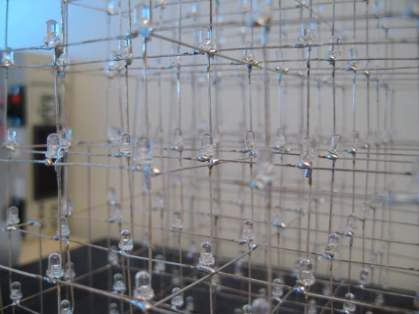
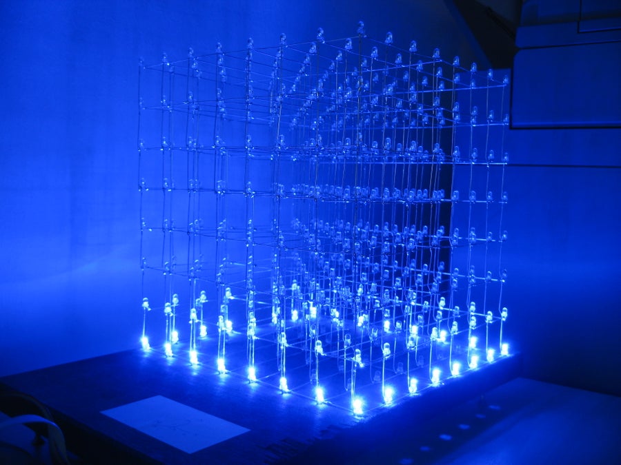


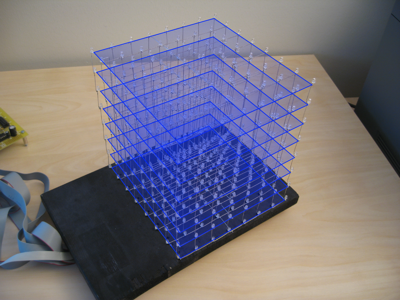
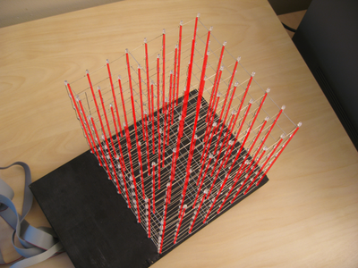

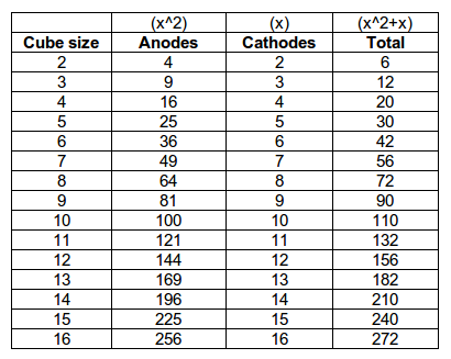
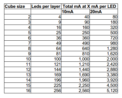
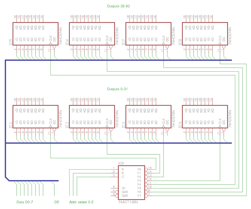


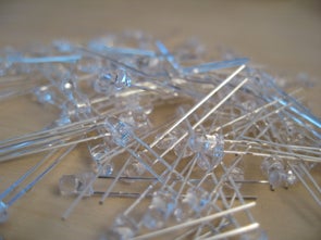


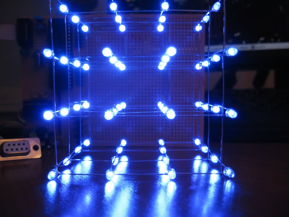

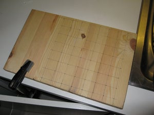
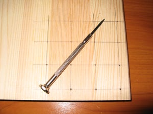


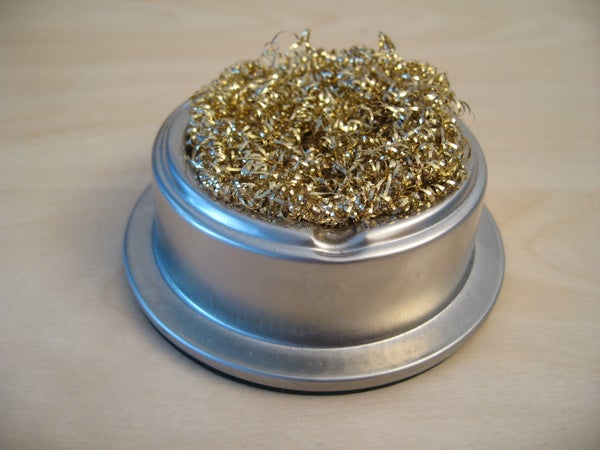


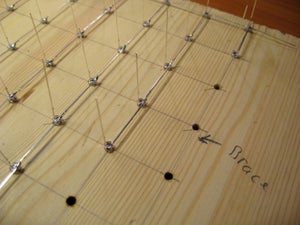


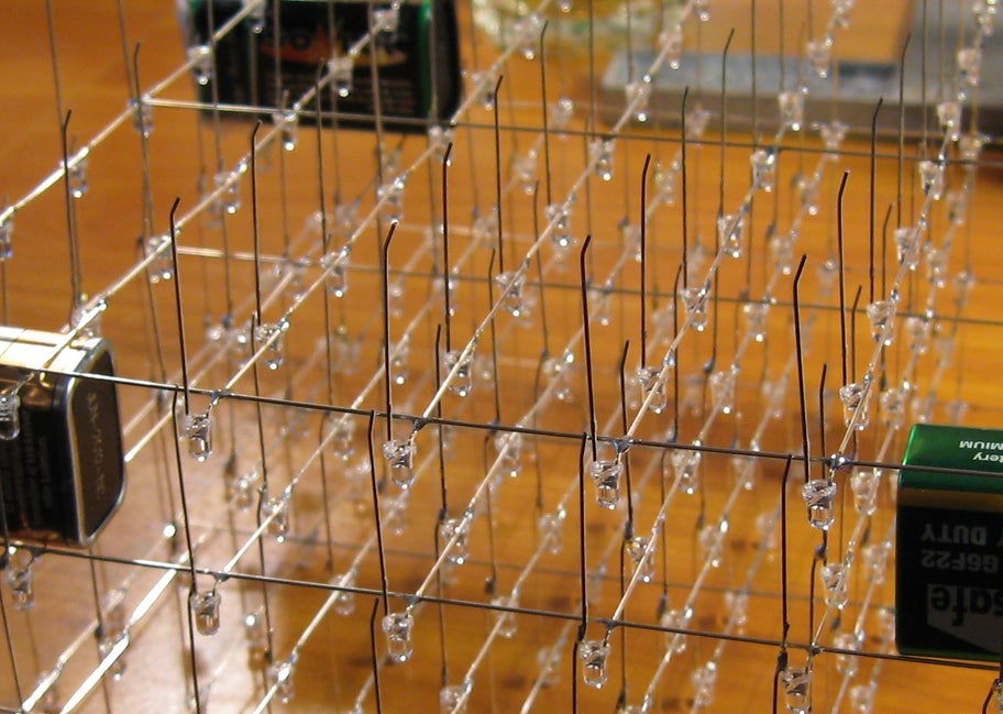


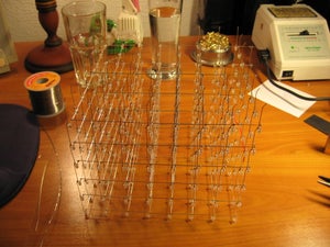

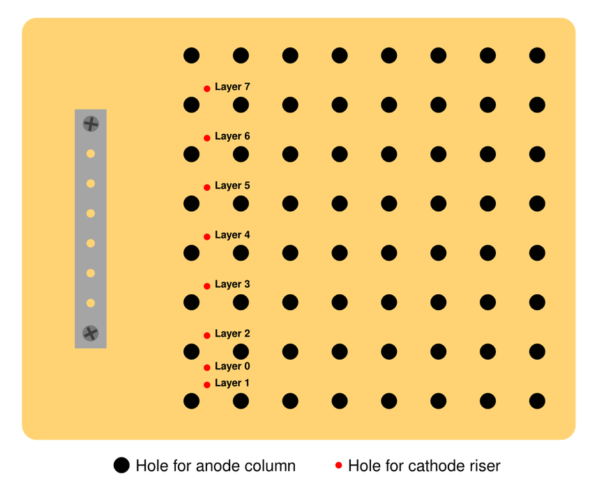
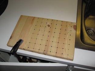


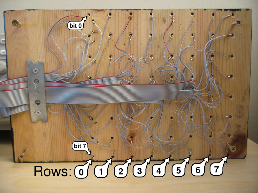


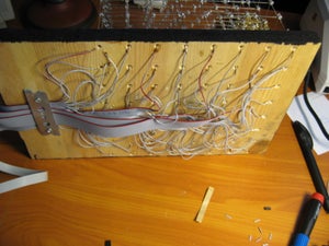
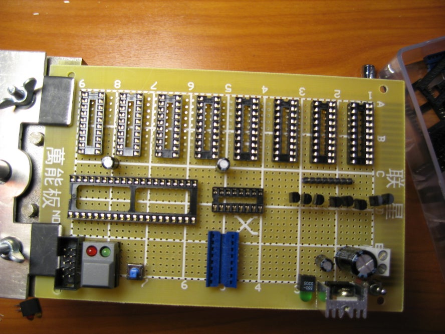
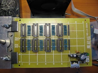


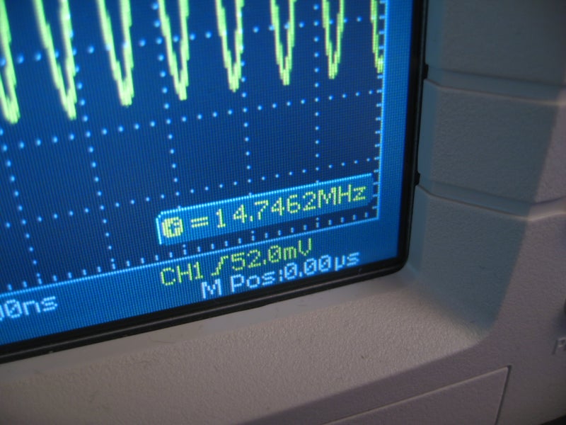
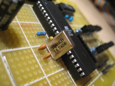

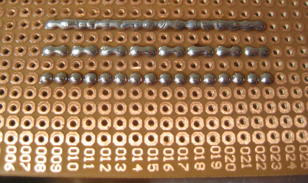
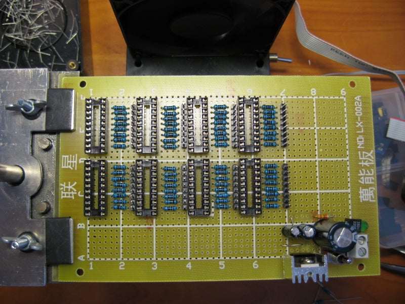


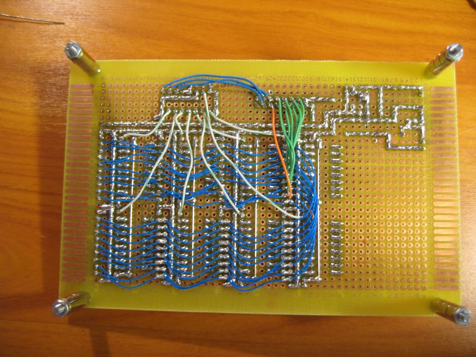
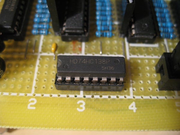
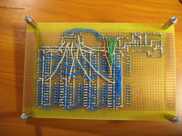
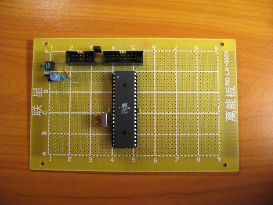
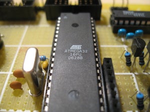


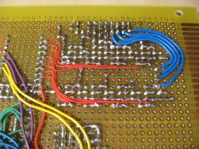
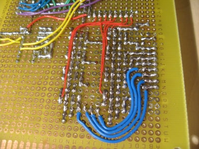

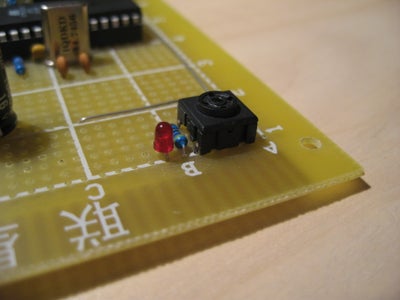
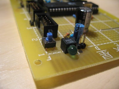
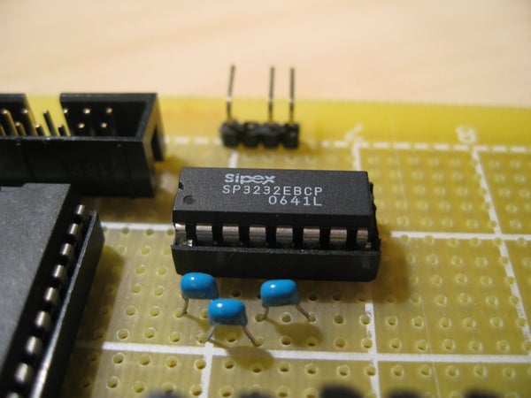
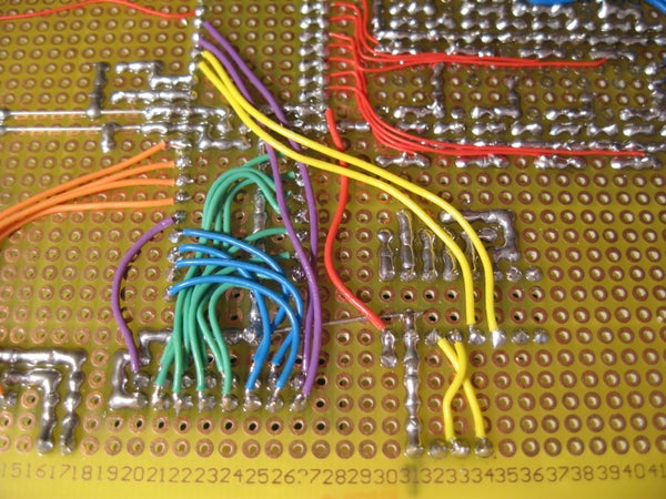


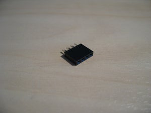


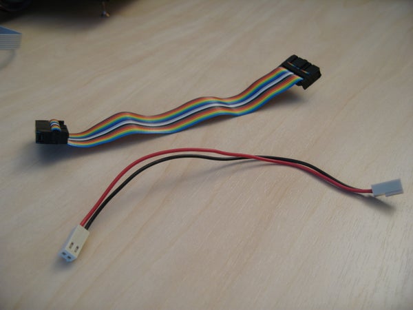


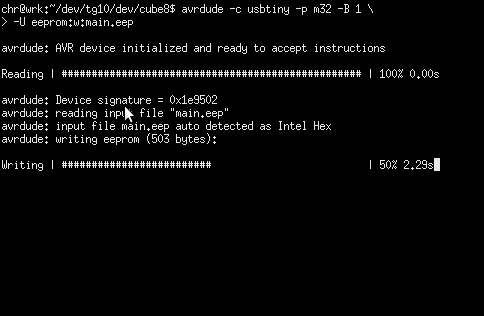


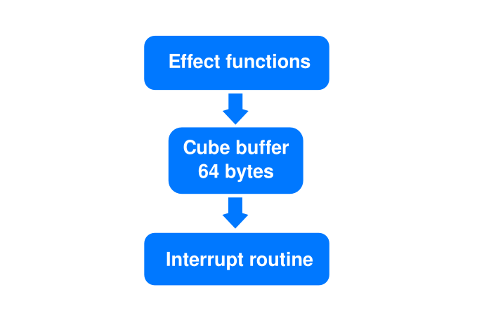


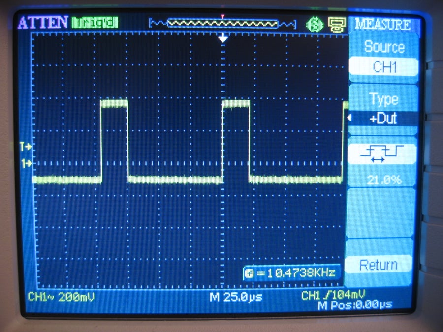

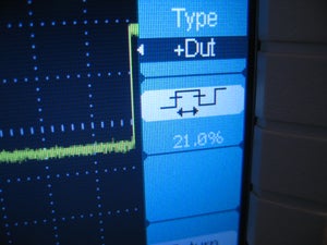
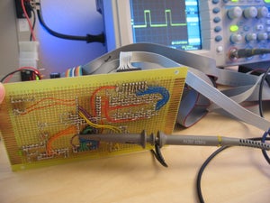


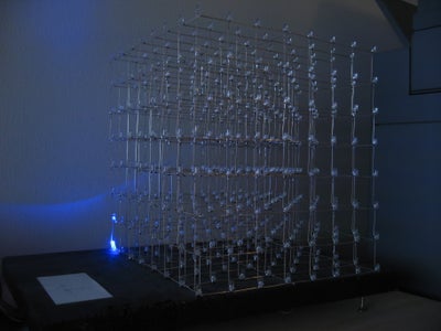
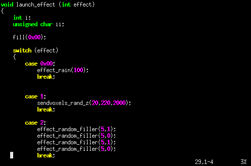
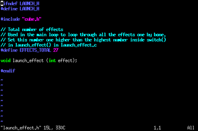
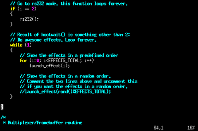
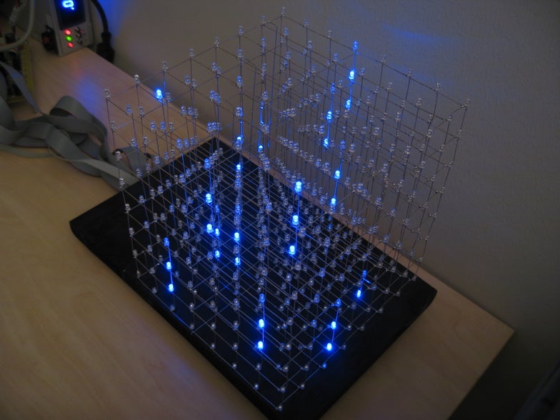
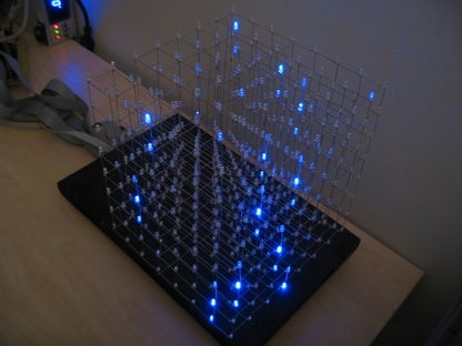
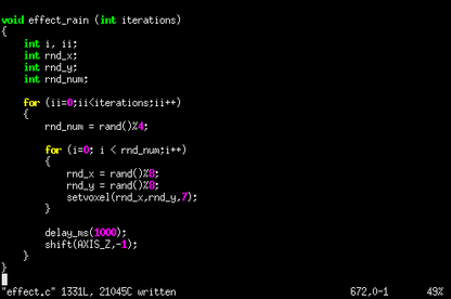


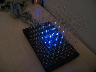
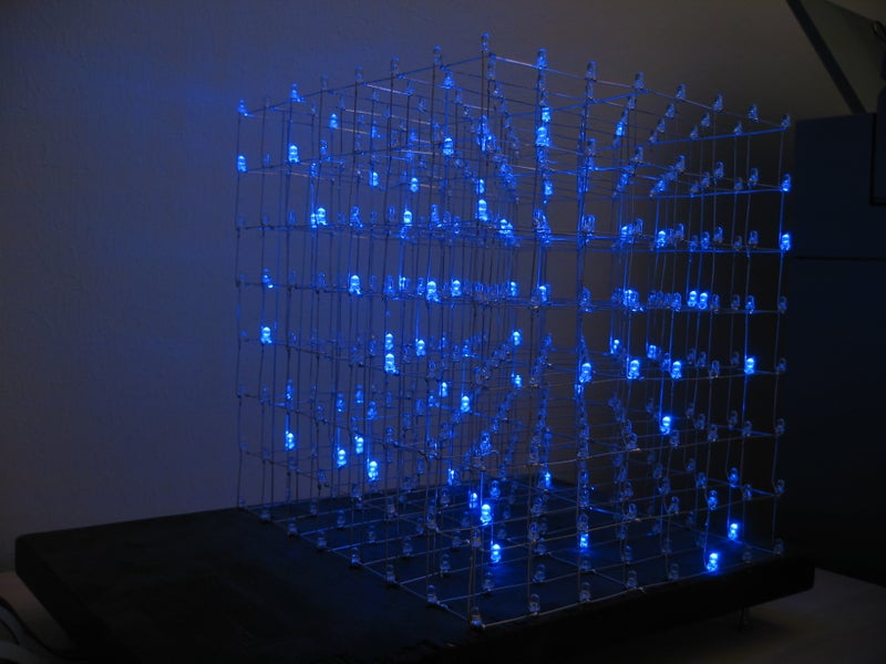

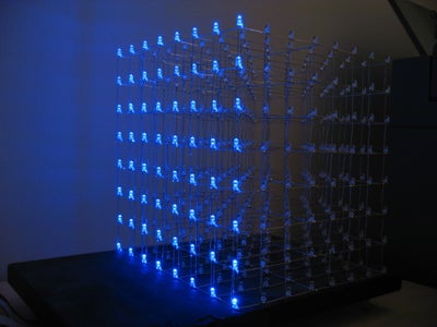


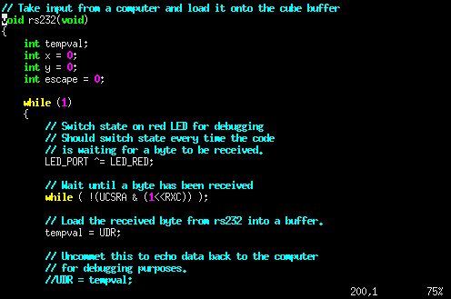

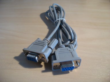


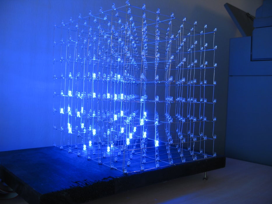

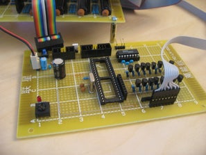


Comments
Post a Comment